1. Introduction
The intelligent eco-house or house (for short) described in this document has been designed within the Erasmus+ EcoThings Project 2021-1-ES01-KA220-SCH-000034349. The purpose of this house is to serve as a mock-up in order to evaluate the set of proposed electronics in the context of an intelligent ecological house using similar principles of real passive houses and energy saving systems. As a consequence, the design has been oriented in providing low-cost solutions, considering as well as manufacturing aspects including 3D printing and laser cutting.
Before reaching the proposed solution, we have explore several ideas in a brainstorming preliminary phase. Ideas were not too much elaborated, and indeed some of them are technically difficult and complex, but during this phase, we were seeking trying to bring new ideas upfront and indeed, some of these ideas were indirectly included in the final version of the proposed prototype, others were simply discarded or left for a future version, due to its complexity.
2. Electronics Description and Connection Diagrams
The following diagram summarizes the connections between the ESP32 microcontroller and selected components. Details about connections will be provided below:

a. Processor (micro-controller)
In the EcoThings Project, we propose to use the ESP32 micro-controller. Other micro-controllers such as Raspberry Pi Pico can be used as well, but the following documentation is just for the implementation using a ESP32.
An ESP32 processor is a microcontroller that has the following features [1]:
- Processor: Xtensa dual-core (or single-core) 32-bit LX6 microprocessor, operating at 160 or 240 MHz and performing at up to 600 DMIPS and ultra low power (ULP) co-processor
- Memory: 320 KiB RAM, 448 KiB ROM
- Wireless connectivity: Wi-Fi: 802.11 b/g/n, Bluetooth: v4.2 BR/EDR and BLE (shared with Wi-Fi).
- Peripherals interfaces: Up to 34 programmable GPIOs, 12-bit SAR ADC up to 18 channels, 2 8-bit DACs, 10 touch sensors, 4 SPI, 2 I²S interfaces, 2 I²C interfaces, 3 UART, SD/SDIO/CE-ATA/MMC/eMMC host controller, SDIO/SPI slave controller, Ethernet MAC interface with dedicated DMA and planned IEEE 1588 Precision Time Protocol support, CAN bus 2.0, Infrared remote controller (TX/RX, up to 8 channels), Pulse counter (capable of full quadrature decoding), Motor PWM, LED PWM (up to 16 channels), Hall effect sensor, ultra low power analog pre-amplifier.
- Security: IEEE 802.11 standard security features all supported, including WPA, WPA2, WPA3 (depending on version)[5] and WLAN Authentication and Privacy Infrastructure (WAPI).
- Secure boot: Flash encryption, 1024-bit OTP, up to 768-bit for customers, cryptographic hardware acceleration: AES, SHA-2, RSA, elliptic curve cryptography (ECC), random number generator (RNG)
- Power management: Internal low-dropout regulator, Individual power domain for RTC; 5 μA deep sleep current; wake up from GPIO interrupt, timer, ADC measurements, capacitive touch sensor interrupt.
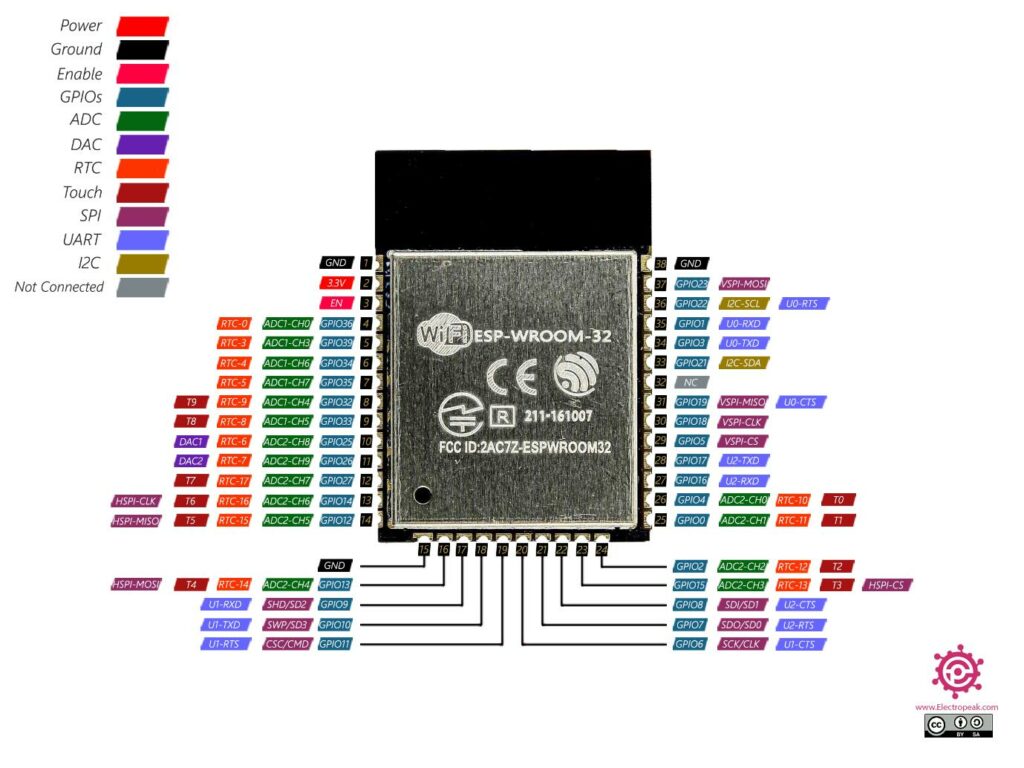
b. ESP32 Pinout
As it can be seen, it includes many peripheral features, but most of them are shared, which means that any pin can be used as a GPIO (general-purpose input/output pin), but they might include also additional features, such as ADC (analog to digital converters), PWM signals, bus signals such as I2C or SPI, etc… [2]
c. Wemos D1R32 board
Wemos D1R32 board (or similar boards such as EspDuino-32) include a ESP32 processor with a pin layout that is compatible with Arduino Uno. Arduino Uno has become a very popular board in the past and many projects propose to use that board as a quick start kit to learn electronics. Wemos D1R32 can be seen as an Arduino Uno board with much more powerful capabilities, including WiFi and Bluetooth, which is ideal for IoT project as well as for compatibility reasons develop basic electronic projects.

It includes a USB connector to easily upload code and Arduino IDE tool (programming tool for Arduino boards) can be used too with this board.
ESP32 has upto 18 ADC pins that use three converters ADC0, ADC1 and ADC2 with multiple channels, which means that depending on the pin used, we will access to a specific hardware resource. However, the Wemos D1R32 board, only some ADC pins are available and distributed as follows:
- ADC1-CH0 (GPIO 36)
- ADC1-CH3 (GPIO 39)
- ADC1-CH6 (GPIO 34)
- ADC1-CH7 (GPIO 35)
- ADC2-CH0 (GPIO 4)
- ADC2-CH2 (GPIO 2)
- ADC2-CH4 (GPIO 13)
- ADC2-CH5 (GPIO 12)
- ADC2-CH6 (GPIO 14)
- ADC2-CH7 (GPIO 27)
- ADC2-CH8 (GPIO 25)
- ADC2-CH9 (GPIO 26)
Another important feature is the use of I2C and SPI buses, because with these buses, we can connect to other compatible devices using much less pins. In particular, the I2C pins are available in the following pins:
- SDA (GPIO 21)
- SCL (GPIO 22)
While SPI (VSPI) pins are available in the following ones:
- MISO (GPIO 19)
- MOSI (GPIO 23)
- CLK (GPIO 18)
- CS (GPIO 5)
PWM signals can be generated using any GPIO pin (programmatically, we can assign attach a pin to a specific PWM channel, upto 16 PWM channels).
Since the board has the same layout as an Arduino board, it is convenient to map pin names used in ESP32 and Arduino Uno (Atmega 328p), so that if we connect on top of the Wemos D1R32 board a shield (that is another electronic with a specific circuit to be used), it is very likely that this shield has been designed originally for Arduino Uno board, so they are physically compatible and (luckily) also electronically compatible (at least in some of the boards we have tested such as the Arduino Uno Sensor Shield and the Multisensor shield).
In particular, we will describe the mapping between the Wemos D1R32 board together with the Arduino Sensor shield, which is basicall a board with many pins that provide easy access to Vcc and Gnd pins as well as signal pins. This is very convenient if we want to avoid using proto-boards with hundreds of cables.

Thus, when using a Wemos D1R32 board and a Arduino Sensor Shield, we will actually connect all devices to the Arduino Sensor Shield that will be indeed connected to the ESP32 processors as follows:
| Wemos D1 R32 | Arduino Uno Sensor Shield | Wemos D1 R32 | Arduino Uno Sensor Shield |
| IO26 | D2 | IO23 | D11 |
| IO25 | D3 | IO19 | D12 |
| IO17 | D4 | IO18 | D13 |
| IO16 | D5 | IO2 | A0 |
| IO27 | D6 | IO4 | A1 |
| IO14 | D7 | IO35 | A2 |
| IO12 | D8 | IO34 | A3 |
| IO13 | D9 | IO36 | A4 |
| IO5 | D10 | IO39 | A5 |
There are multiple ways to connect living room electronics to the ESP32 through the Arduino Shield. Here, we propose a specific connection setting:
| Component | PIN NAME | ESP32 PIN | Arduino Shield |
| NTC Sensor | Analog Input | 36 | A4 |
| Resistors 120Ω | Digital Output | 26 | D2 |
| FAN | Digital Output | 17 | D4 |
| Living Room Servo | Digital Output | 25 | D3 |
| TFT Screen | TFT_CLK | 18 | D13 |
| TFT_SDA | 23 | D11 | |
| TFT_CS | 13 | D9 | |
| TFT_RST | 5 | D10 | |
| TFT_RS | 27 | D6 | |
| ESP32 Cam with Infrared Sensor | I2C | 21 | SDA |
| 22 | SCL |
With this electronic proposal, we can regulate the room temperate and safe some energy in a smart way. We can also display interesting variables on the screen just to monitor actual energy saved/consumed, room temperature and any other variable of interest. Here you can find a full connection diagram as well as some circuit examples to start coding with the proposed electronics.
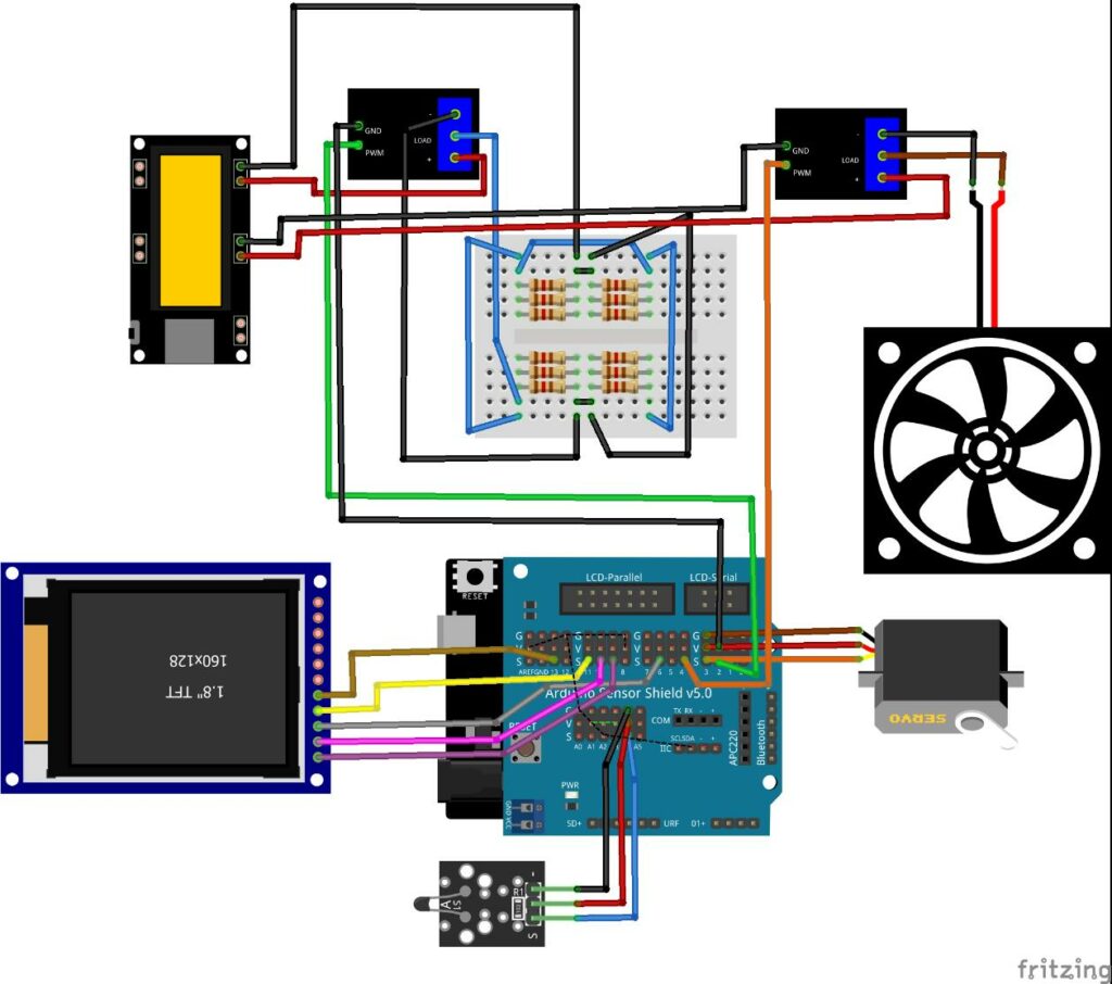
Breadboard connection example:

Resistor and motor control:
https://www.tinkercad.com/things/5t1euEOYuPw
Temperature control:
https://www.tinkercad.com/things/eQBM9LuhSOn
Passive House example:
https://www.tinkercad.com/things/2ZwHmyCP0P9
3. Passive House Logic
Assuming that the temperature of the ground coming from the ventilation system (fan) is constant and fixed to 19ºC, we can stablish a temperature control policy based on the outside temperature (assumed to be provided via an external service such as a OpenWeather), room temperature (from NTC sensor) and setpoint temperature (user sets this temperature). Also considering that the amount of long-term energy of a heater is much higher that activating a fan and at the same time the energy required to activate the fan is higher than the energy required to open the window, we can stablish the following rules:
| Temperatures | Heater | Fan | Window |
| Room<Ground<Setpoint<Outside | Off | Off | Open |
| Room<Ground<Outside<Setpoint | On | Off | Closed |
| Room<Setpoint<Ground<Outside | Off | Off | On |
| Room<Setpoint<Outside<Ground | Off | Off | Open |
| Room<Outside<Ground<Setpoint | On | Off | Closed |
| Room<Outside<Setpoint<Ground | Off | On | Off |
| Ground<Room<Setpoint<Outside | Off | Off | On |
| Ground<Room<Outside<Setpoint | On | Off | Off |
| Ground<Setpoint<Room<Outside | Off | On | Closed |
| Ground<Setpoint<Outside<Room | Off | On | Closed |
| Ground<Outside<Room<Setpoint | On | Off | Closed |
| Ground<Outside<Setpoint<Room | Off | Off | Open |
| Setpoint<Room<Ground<Outside | Off | Off | Closed |
| Setpoint<Room<Outside<Ground | Off | Off | Closed |
| Setpoint<Ground<Room<Outside | Off | On | Closed |
| Setpoint<Ground<Outside<Room | Off | On | Closed |
| Setpoint<Outside<Room<Ground | Off | Off | Open |
| Setpoint<Outside<Ground<Room | Off | Off | Open |
| Outside<Room<Ground<Setpoint | On | Off | Closed |
| Outside<Room<Setpoint<Ground | Off | On | Closed |
| Outside<Ground<Room<Setpoint | Off | Off | Closed |
| Outside<Ground<Setpoint<Room | Off | Off | Open |
| Outside<Setpoint<Room<Ground | Off | Off | Open |
| Outside<Setpoint<Ground<Room | Off | Off | Open |
f. Bedroom connections
The proposed connections for the bedroom (considering that there are pins that are already being used by the electronics of the living room) is as follows:
| Component | PIN NAME | ESP32 PIN | Arduino Shield |
| LDR Sensor | Analog Input | 39 | A5 |
| MIC Sensor | Analog Input/Digital Input | 35 | A2 |
| PIR Sensor | Digital Input | 2 | A0 |
| Bedroom Servo | Digital Output | 4 | A1 |
| RGB LED Strip | Digital Output | 12 | D8 |
With this electronic proposal, we can measure light and sound as well as detect the presence of someone in the room and then decide wether or not to switch on or off the lights and to open and close the window. Information about weather temperature as well as sunrise and sunset hours can be obtained via an IoT service, which might be useful also to help on the decision process.

Breadboard connection example (mic not included because is not available in TinkerCAD):
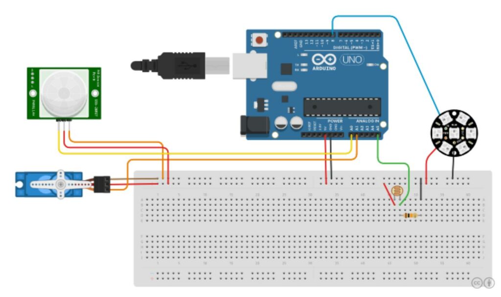
https://www.tinkercad.com/things/kb9ghMm3gYx
The proposed connection for the kitchen (considering that there are pins that are already been used by the electronics of the living room and bedroom) is as follows:
| Component | PIN NAME | ESP32 PIN | Arduino Shield |
| Gas Sensor | Analog Input/Digital Input | 34 | A3 |
| Buzzer | Digital Output | 16 | D5 |
| Flame Sensor | Digital Input | 19 | D12 |
| Kitchen Servo | Digital Output | 14 | D7 |
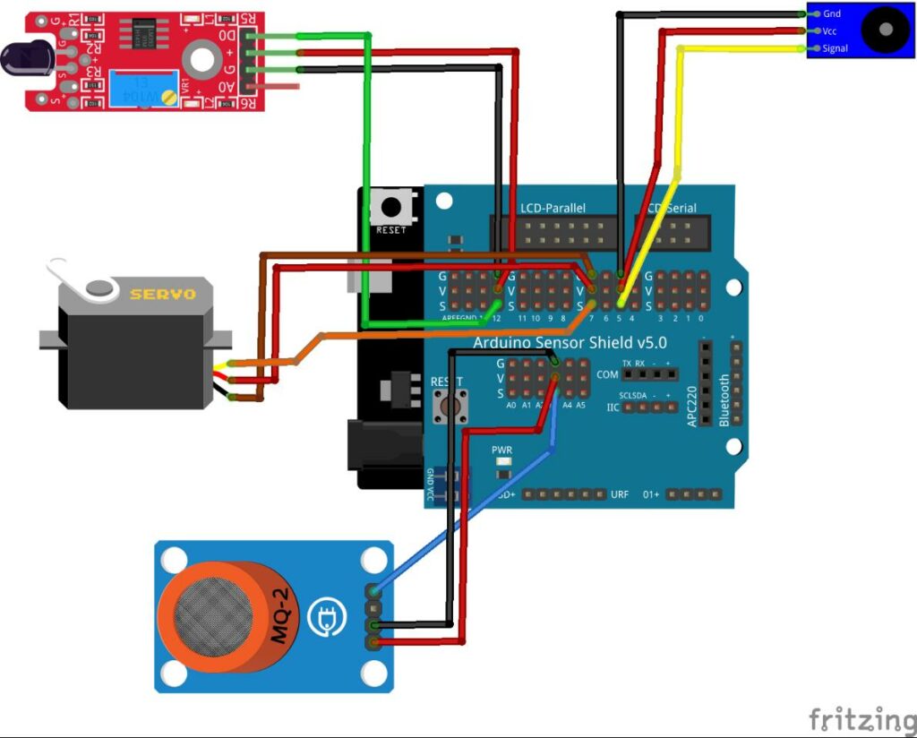
Breadboard connection example:
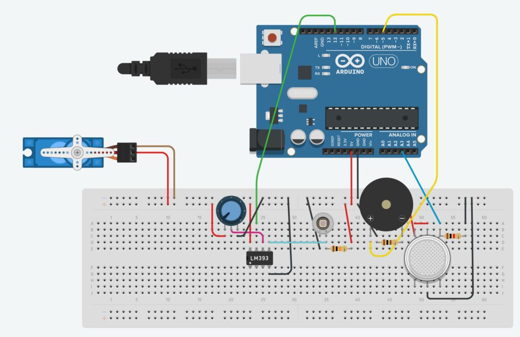
https://www.tinkercad.com/things/dGslUCgacXQ

PIR sensor:
PIR sensor SR602 is a pyroelectric infrared sensor, which allows for detecting the motion of
humans. This sensor can detect movement from a distance of up to 5 meters, although the best results will be achieved when the human is up to 3.5 meters away.

Appendices

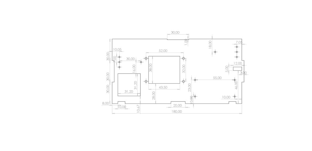
b. Part #2 Livingroom rear wall

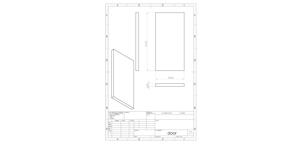
d. Parts #4, #18, #19 Door
a. KY-013 Analog Temperature Sensor module (NTC Sensor)
The KY-013 Analog Temperature Sensor module can measure ambient temperature based on the resistance of the thermistor on the board [3]. This module consists of a NTC thermistor connected to a 10 kΩ resistor. The thermistor resistance varies according to its surrounding temperature, thus, acting as a voltage divider, we can measure the temperature by measuring the output voltage. The relation between such voltage and temperature is non-linear, but their parameters are known based on the Steinhart-Hart equation [4].

b. KY-026 Flame Sensor module
The KY-026 Flame Sensor module detects infrared light emitted by fire
https://arduinomodules.info/ky-026-flame-sensor-module

c. LDR KY-018 module (LDR sensor)
The KY-018 uses a Light dependent resistor (LDR) to measure light intensity (the resistance will decrease in the presence of light).

https://arduinomodules.info/ky-018-photoresistor-module
d. Pyroelectric Infrared Sensor
Passive buzzer:
To generate melodies and alarms.
https://arduinomodules.info/ky-006-passive-buzzer-module

RGB LED strips

Mosfet module:
Any of these two, can be used to generate a high power analog output (driven by a PWM signal).
Mosfet module 400W 15A ICQUANZX

LR7843 MOSFET / FR120N MOSFET


Relay module:
If we use a relay, we can not generate analog outpus (PWM)
https://arduinomodules.info/ky-019-5v-relay-module/

Servos SG90
Position controlled motor
https://www.circuitschools.com/how-to-control-servo-motor-with-arduino-and-how-they-work/
1. Living room

Bill of materials:
| Name | Quantity | Component |
| R1-R12 | 12 | 100Ω resistor |
| P1 | 1 | Powerbank |
| R13-R14 | 2 | 1kΩ resistor |
| U1 | 1 | Arduino Uno (or Wemos D1R32) |
| U2 | 1 | Photodiode |
| Q1-Q2 | 2 | TIP120 |
| M1 | 1 | Fan motor |
| D1 | 1 | Diode |
2. Bedroom

Bill of materials:
| Name | Quantity | Component |
| U1 | 1 | Arduino Uno (or Wemos D1R32) |
| Servo1 | 1 | Position servo |
| Jewel1 | 1 | NeoPixel Jewel |
| PIR1 | 1 | PIR sensor |
| R1 | 1 | Photoresistor |
| R2 | 1 | 10kΩ resistor |
3. Kitchen

Bill of materials:
| Name | Quantity | Component |
| U1 | 1 | Arduino Uno (or Wemos D1R32) |
| GAS1 | 1 | Gas sensor |
| Servo1 | 1 | Position servo |
| Piezo1 | 1 | Piezo electric buzzer |
| U2 | 1 | Photodiode |
| R1 | 1 | 1kΩ resistor |
| U3 | 1 | OAmp (comparer) |
| R2 | 1 | 10kΩ resistor |
| Rpot1 | 1 | 10kΩ potentiometer |
| R3 | 1 | 100Ω resistor |
References
[1] https://en.wikipedia.org/wiki/ESP32
[2] Electropeak.com
[3] https://arduinomodules.info/ky-013-analog-temperature-sensor-module/
[4] https://en.wikipedia.org/wiki/Steinhart%E2%80%93Hart_equation
